 FLEXIBLE CABLE PUSHRODS: Flexible cable pushrods are usually the best choice for hooking up the throttle and nosewheel steering because they are the most flexible kind of pushrod you can get. A flex-cable pushrod consists of a stranded steel cable sliding inside of a nylon outer tube. Due to its great flexibility, it is easy to navigate the cable pushrod from the servo, around the fuel tank, and onto the throttle or steering arm.
TIPS ON INSTALLING A FLEX-CABLE THROTTLE PUSHROD
The most common mistake is to leave too long a length of steel cable unsupported, so that it bows up and down when subjected to load. To prevent this, run the outer nylon tube up fairly close to the servo and to the control horn at the other end. Glue the nylon outer tube securely to the model structure in 2 or 3 places, particularly near both ends of the tube. The outer tube should not be floating loose! Also, it helps to stiffen the ends of the steel cable that stick out past the outer tube by tinning the cable with solder. Use a hot soldering iron and just enough solder to fill the strands of the cable; too much will increase the diameter of the cable and make it bind inside the outer tube.
Start the installation of the pushrod by mounting the engine and the throttle servo in the model. Drill a hole through the firewall large enough for the nylon outer tubing to pass through. Locate the hole carefully, so that the pushrod will be aimed directly at the engine's throttle control arm. Direct the pushrod tubing with the cable inside (no end fittings yet) through the hole and around the fuel tank towards the throttle servo arm. Try some experimental routes to find the best angle to approach the servo with the cable so it will not bind. Push and pull the cable back and forth through the tubing to find out if it moves freely. Trial and error-will determine the best route to follow with the pushrod in your model. Once you are satisfied with the intended route, tack glue the nylon outer tubing to the firewall and then slide the steel cable out of the tube.
You will want to install an adjustable R/C link on the engine end of the throttle pushrod so you can make fine adjustments when setting up the carburetor at the field. A "threaded coupler" should be soldered onto the end of the cable to provide threads for the R/C link. Prepare the cable, as shown below, before soldering. When cool, screw a nylon R/C link halfway onto the threaded coupler (avoid using metal clevises on metal throttle arms - this could cause electrical "noise" that might affect your radio). Feed the other end of the cable back into the nylon tube from the front, push it all the way back into the fuselage until the R/C link can be snapped onto the engine's throttle control arm. Check the movement of the throttle one last time by working the servo end of the cable by hand. It should be smooth and free! Then glue the outer tube permanently into me hole in the firewall, leaving as much as possible extending forward to support the cable.
The servo end of the throttle pushrod generally needs a scrap balsa block to support the end of the nylon outer tubing. Shape the block so that it will point the tube directly at the servo arm, and then glue it to the fuselage side about two inches ahead of the servo's output arm and at the same height as the arm. When satisfied that it will work without binding, permanently glue the nylon outer tube to the support block. Cut the tube and cable to final length needed to accept your choice of servo connector.
PREPARING CABLE PUSHRODS
To keep the ends of the cable from unraveling during handling and make it easier to insert pushrod fittings, tin the end of
the cable with solder. Use a very hot iron to heat the cable and then flow solder completely through the strands.
When cool, grind or file the tinned end smooth. Taper it down slightly so that it will go into the pushrod fittings and
nylon outer tube easily.
|

|
|
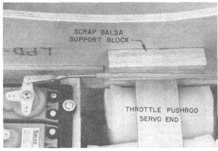 LEFT: The scrap balsa sup port block must be careful! shaped to line up the throt tie pushrod with the serv output arm. Roughen th nylon tubing with sandpape before gluing it with cpov or cyanoacrylate adhesive
BELOW: This photo clear ly shows the flexible cabl throttle pushrod, the solder ed-on threaded coupler, am the nylon R/C link hookec up to the throttle arm on II* engine's carburetor.
